Boot from Flash
Creating Container image
Container image is stored in raw format on flash partition without using EXT2 or FAT file system. See Create Container Boot Image for more details.
Note
Container image max size is 0x700000. Exclude Initrd file during Container image creation to reduce size.
Place the image in platform folder
Create folder SpiContainerBin/ in platform folder of specific project.
Example: Platform/<ProjectBoardPkg>/SpiContainerBin
Copy Container binary image into SpiContainerBin folder.
Note
Container image should be named as containerimage1.bin for 1st Container region and containerimage2.bin for second Container region.
Adding Container to BIOS region
Step 1: Add containerimage1.bin to non-redundant region of BIOS region.:
('SPI_CONTAINER1.bin' , '' , self.SPI_CONTAINER1_SIZE, STITCH_OPS.MODE_FILE_PAD | container1_flag, STITCH_OPS.MODE_POS_TAIL)
Step 2: Define size of the container image:
self.SPI_CONTAINER1_SIZE = 0x700000
Step 3: Increase non-redundant area size by size of the container image:
self.NON_REDUNDANT_SIZE = X + self.SPI_CONTAINER1_SIZE
Step 4: Increase slim bootloader size to maximum depending on the platform:
self.SLIMBOOTLOADER_SIZE = 0x01000000 (16 MB)
Step 5: Define container image flag:
container1_flag = 0 if self.SPI_CONTAINER1_SIZE > 0 else STITCH_OPS.MODE_FILE_IGNOR
Step 6: Remove any redundant region to create space for Container image:
#('REDUNDANT_B.bin' , '' , self.REDUNDANT_SIZE,STITCH_OPS.MODE_FILE_PAD, STITCH_OPS.MODE_POS_HEAD)
Boot options for Boot from BIOS region
See Boot Options for more details.
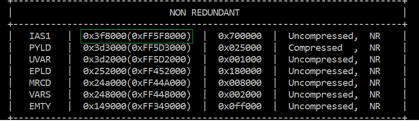
Step 1: Get LBA address from flash map during build. For example refer below image, 0x622f90 is the LBA offset of Container image.
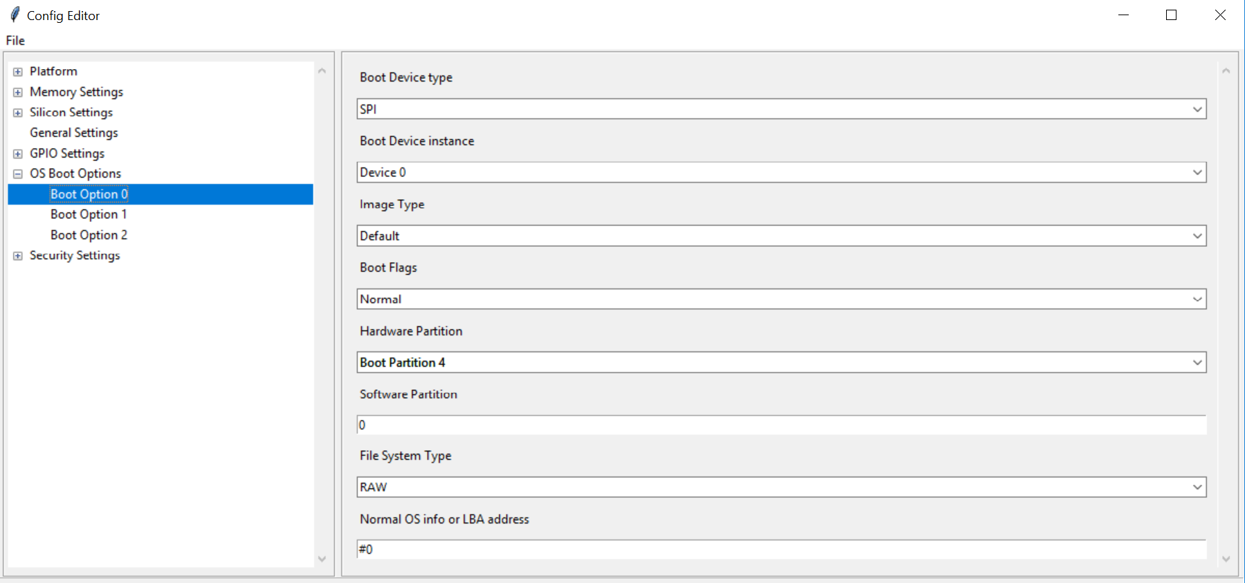
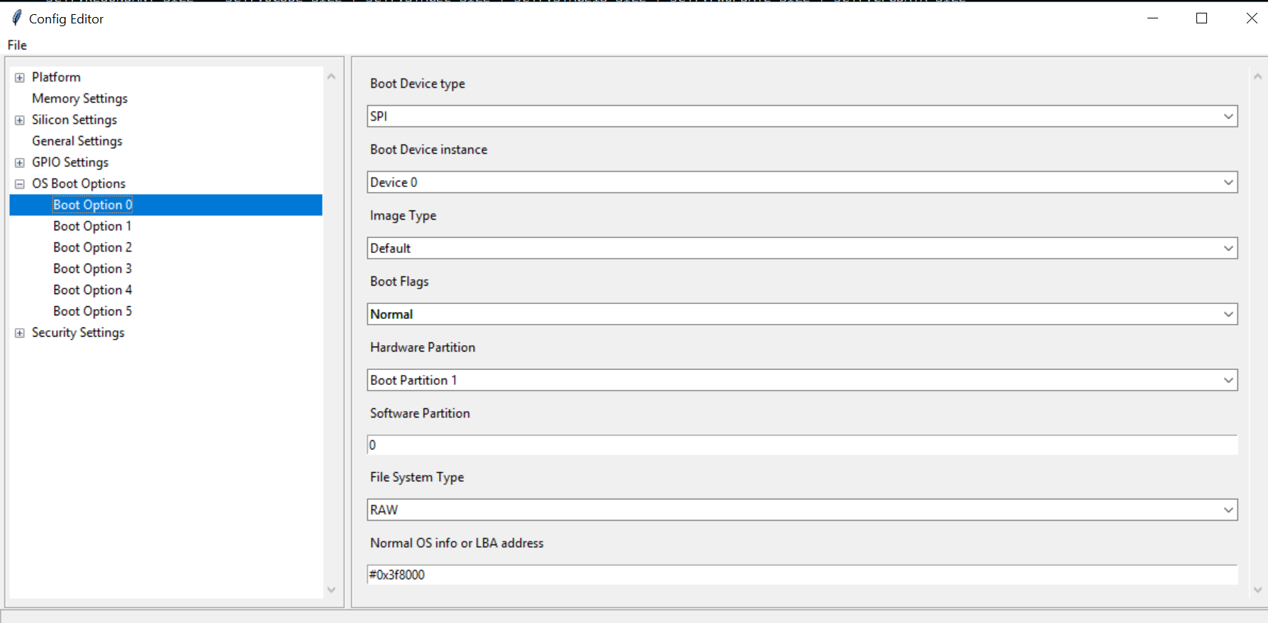
Step 2: Config boot options in config editor as below to boot from BIOS.
Adding Container to PDR region using Stitching
Container image can be added to PDR region in two ways using stitching or using FIT tool.
Using Stitching method.
Step 1: To place the image in PDR region, add the below changes to StitchIfwiConfig.py in function get_xml_change_list().:
('./FlashLayout/Regions/PdrRegion/Length', '0x700000'),
('./FlashLayout/Regions/PdrRegion/InputFile', '$SourceDir\containerimage1.bin'),
('./FlashLayout/Regions/PdrRegion/Enabled', 'Enabled'),
Step 2: Copy containerimage1.bin to ‘Input/containerimage1.bin’
Step 3: Stitch the final image.
Adding Container image to PDR using FIT tool.
Step 1: Open the IFWI using FIT tool.
Step 2: Load Container image into PDR region.
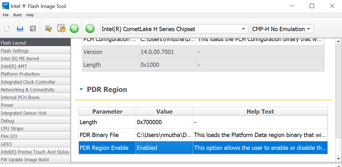
Step 3: Build the image.
Boot options for Boot from PDR
Step 1: Change boot options as below.